Self-Heating LiFePO4 Batteries: The Science of Cold Weather Performance Wiltson Energy
Blog Post Part 1
The Thermal Paradox of LiFePO4 & The Self-Heating Solution
1. Introduction: The Thermal Paradox of Lithium Iron Phosphate
The global transition toward decentralized renewable energy systems has been largely underpinned by the maturation of Lithium Iron Phosphate (LiFePO4 or LFP) battery chemistry. Characterized by a robust olivine crystal structure that offers exceptional thermal stability, cycle lives exceeding 4,000 cycles, and a localized safety profile superior to Nickel Manganese Cobalt (NMC) oxides, LFP has become the de facto standard for deep-cycle energy storage in stationary, marine, and recreational applications.
However, this chemistry faces an inherent thermodynamic paradox: while it is exceptionally stable at high temperatures compared to other lithium-ion variants, its performance metrics precipitously degrade as the ambient temperature approaches the freezing point of water.
The challenge is not merely one of reduced capacity, which is a reversible phenomenon, but of catastrophic and irreversible damage during charging operations in sub-zero environments. As the deployment of energy storage systems expands into high-latitude regions, high-altitude environments, and stratospheric aerospace applications, the industry has been forced to bifurcate its engineering focus into two distinct remedial pathways.
1.1 The Physics of the "Cold Cliff"
To understand the necessity of these interventions, one must first appreciate the severity of the "cold cliff"—the sharp decline in electrochemical performance that occurs as temperatures drop. Standard LFP batteries operate optimally between 0°C and 45°C.
Below this range, the Arrhenius equation dictates that reaction rates slow exponentially. Specifically, the viscosity of standard carbonate-based electrolytes increases, impeding the migration of lithium ions (Li+) between the cathode and anode.
Simultaneously, the charge-transfer resistance (\(R_{ct}\)) at the electrode-electrolyte interface spikes. The desolvation energy barrier—the energy required for a lithium ion to strip off its solvent shell and intercalate into the graphite anode—becomes insurmountable at high currents. This resistance results in severe voltage sag under load, often triggering low-voltage cutoffs (LVC) in battery management systems (BMS) even when the battery holds a substantial state of charge (SoC).
1.2 The Threat of Lithium Plating
The most acute danger, however, lies in the charging process. In standard operating conditions, lithium ions intercalate into the porous graphite structure of the anode. At sub-freezing temperatures, the diffusion rate of ions into the carbon lattice becomes slower than the rate at which ions arrive at the anode surface during charging. This kinetic mismatch causes the electrochemical potential of the anode to drop below 0 V relative to \(Li/Li^+\), creating thermodynamically favorable conditions for the reduction of lithium ions into metallic lithium on the anode surface.
This phenomenon, known as lithium plating, is deleterious for three reasons:
Capacity Loss: The plated lithium is often chemically isolated ("dead lithium"), permanently removing it from the active inventory and reducing total capacity.
Dendrite Formation: Metallic lithium tends to grow in needle-like dendritic structures. Over time, these dendrites can pierce the polymer separator, causing internal short circuits and potential thermal events, although LFP is chemically less prone to thermal runaway than cobalt-based chemistries.
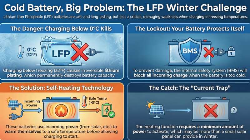
Safety Lockouts: To prevent this, manufacturers universally program BMS logic to terminate charging at 0°C (32°F), rendering the battery effectively useless for recharging in winter conditions without external intervention.
2. Electrochemistry of the Frozen Cell: A Deep Dive
Before analyzing the solutions, we must rigorously define the problem variables. The performance of a lithium-ion cell at low temperature is governed by the conductivity of the electrolyte (\(\kappa\)), the solid electrolyte interphase (SEI) resistance, and the solid-state diffusion coefficient (\(D_{Li}\)).
2.1 Electrolyte Viscosity and Ionic Transport
Standard electrolytes utilize Ethylene Carbonate (EC) as a primary solvent due to its high dielectric constant (\(\epsilon \approx 89\)), which effectively dissociates lithium salts like \(LiPF_6\). However, EC has a high melting point of 36.4°C and is solid at room temperature, requiring the addition of co-solvents like Dimethyl Carbonate (DMC) or Diethyl Carbonate (DEC) to form a liquid solution.
As temperatures drop to -20°C or -30°C, the viscosity of these mixtures increases drastically. According to the Stokes-Einstein equation, the diffusion coefficient of an ion is inversely proportional to the viscosity of the medium. Consequently, ionic conductivity plummets. Research indicates that standard LFP electrolytes may lose over 80-90% of their ionic conductivity when temperatures shift from 25°C to -30°C.
This manifests in the user experience as a battery that appears "dead"—showing voltage, but collapsing instantly under any significant load due to massive internal resistance (IR) voltage drop (\(V_{drop} = I \times R_{internal}\)).
3. Technological Pathway A: Active Thermal Management (Self-Heating Batteries)
The "Self-Heating" or "Heated" LiFePO4 battery represents an engineering workaround to the chemical limitations of the cell. Rather than altering the fundamental chemistry and risking trade-offs in longevity or stability, this approach integrates an active heating system to create a micro-climate for the cells.
3.1 Architecture and Hardware Implementation
The physical construction of a self-heating battery involves the integration of resistive heating elements within the battery case.
3.1.1 Heating Element Technology
Most commercial implementations, such as those by Battle Born, Relion, and Renogy, utilize thin-film polyimide (Kapton) heaters or silicone heating pads placed between the prismatic cells or wrapped around the cylindrical cell bank. These materials are chosen for their high dielectric strength, thin profile, and ability to transfer heat rapidly to the aluminum cell casings.
The heating power is significant. For a standard Group 31 100Ah battery (approx. 1280Wh), heater power consumption typically ranges from 20W to 120W depending on the design intent. Battle Born’s system draws approximately 1.8A at ~13V (~24W) for a steady, gentle heat, while Relion’s LT series creates a heating load that can consume up to 10A (~130W) to rapidly bring the battery to operational temperature.
3.1.2 Sensors and Control Loop
The brain of the operation is the BMS. It utilizes internal thermistors to monitor cell temperature. The control logic is typically a hysteresis loop:
Activation Condition: If \(T_{cell} < 0^{\circ}C\) AND Charge Current \(> Threshold\), engage heater.
Heating Phase: Divert incoming charge current to the heating element. Do not allow current to flow to the cells (preventing plating).
Deactivation Condition: If \(T_{cell} > 5^{\circ}C\) (typical buffer), disengage heater and open the FETs for charging.
3.2 Power Source Logic and Energy Balance
A critical differentiator in self-heating designs is the source of the heating energy.
3.2.1 Parasitic Load vs. Harvested Energy
Most consumer-grade deep-cycle batteries utilize Charger-Driven Heating. They do not use the stored energy in the battery to heat themselves while in storage, as this would deplete the battery and potentially ruin it during long winter storage periods. Instead, they "harvest" the energy from the solar controller or alternator.
Implication for Users: There is a "dead time" or "latency period." When a user starts their vehicle or the sun comes up, the battery does not immediately charge. It acts as a resistive load. For a 100Ah battery at -20°C, it may take 1 to 2 hours of heating before the BMS allows charging to commence.
3.2.2 The "Current Threshold" Trap
A significant issue identified in field applications is the activation current threshold. Some BMS designs require a minimum current (e.g., 5A or even 20A) to activate the heating circuit effectively.
Scenario: A user has a single 100W solar panel in winter producing 3A. The BMS sees 3A, which might be insufficient to power the heating pad (which needs 5A). The system enters a deadlock: it cannot charge because it is cold, and it cannot heat because the current is too low.
3.3 Pros and Cons: The Self-Heating Approach
Feature
Advantages
Disadvantages
Cycle Life
Superior: Utilizes standard LFP chemistry, retaining the full 3000-5000 cycle rating.
None: The heating system preserves the cells by preventing cold-charging damage.
High-Temp Performance
Excellent: Standard electrolyte is stable up to 60°C; no degradation trade-off.
None: Heating pad is inactive in summer.
Integration
Drop-in: Retrofit-friendly. Works with standard chargers (mostly).
Current Dependency: Requires sufficient external current to initiate heating; incompatible with small trickle chargers.
Latency
N/A
High: Battery is not available for charging immediately; must wait for heating cycle (up to hours).
(Part 2, where we dive into the chemical engineering breakthroughs of Low-Temperature Electrolytes and compare them head-to-head with self-heating options.)